Aa Bb Cc Dd Ee Ff Gg Hh
Ii Jj Kk Ll Mm Nn Oo Pp Qq
Rr Ss Tt Uu Vv Ww Xx Yy Zz
1 2 3 4 5 6 7 8 9 0
! @ # $ % ^ & * ( ) - _ =
+ [ ] { } ; : ' " < > , . / ?
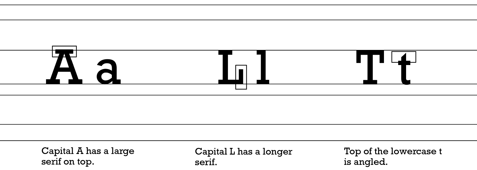
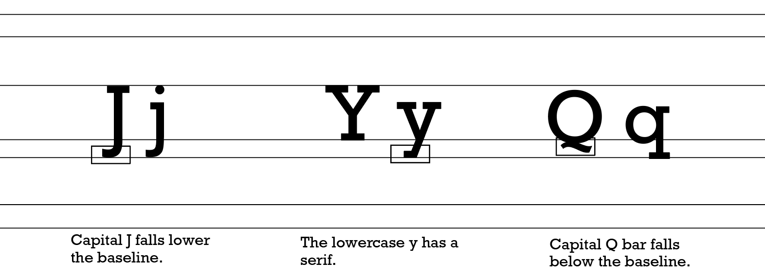
Rockwell Regular
Aa Bb Cc Dd Ee Ff Gg Hh
Ii Jj Kk Ll Mm Nn Oo Pp Qq
Rr Ss Tt Uu Vv Ww Xx Yy Zz
1 2 3 4 5 6 7 8 9 0
! @ # $ % ^ & * ( ) - _ =
+ [ ] { } ; : ' " < > , . / ?
Rockwell Bold
B
Aa Bb Cc Dd Ee Ff Gg Hh
Ii Jj Kk Ll Mm Nn Oo Pp Qq
Rr Ss Tt Uu Vv Ww Xx Yy Zz
1 2 3 4 5 6 7 8 9 0
! @ # $ % ^ & * ( ) - _ =
+ [ ] { } ; : ' " < > , . / ?
Rockwell Italic
Aa Bb Cc Dd Ee Ff Gg Hh
Ii Jj Kk Ll Mm Nn Oo Pp Qq
Rr Ss Tt Uu Vv Ww Xx Yy Zz
1 2 3 4 5 6 7 8 9 0
! @ # $ % ^ & * ( ) - _ =
+ [ ] { } ; : ' " < > , . / ?
Rockwell Bold Italic
Manual Pdf - Hydraulic Institute Pipe Friction
Practical Applications
h sub f equals f center dot the fraction with numerator cap L and denominator cap D end-fraction center dot the fraction with numerator v squared and denominator 2 g end-fraction : Friction factor : Length of pipe : Internal diameter : Velocity : Acceleration due to gravity Reynolds Number ( : Used to determine if flow is laminar ( ) or turbulent ( Relative Roughness (
Whether you are looking for a digital PDF version for daily engineering work or trying to understand how to apply its charts and data, this comprehensive guide covers everything you need to know about this essential fluid mechanics reference. What is the Hydraulic Institute Pipe Friction Manual?
Piping systems are rarely straight lines. Every bend, valve, tee, and reducer disrupts the fluid velocity profile, causing localized turbulence and additional head loss. These are known collectively as "minor losses," though they can often exceed straight-pipe friction losses in complex plants.
: Predetermined head loss values for water (usually in feet per 100 feet of pipe) across various pipe schedules (Schedule 40, 80) and sizes. Viscosity Corrections hydraulic institute pipe friction manual pdf
Easily copy formula parameters or table data directly into design software, spreadsheets, or proprietary calculators.
For fluid mechanics engineers, pump system operators, and facilities managers, downloading or referencing a digital version of this text ensures that hydraulic systems are sized correctly to avoid excessive energy costs, mechanical wear, or system failure. What is the Hydraulic Institute Pipe Friction Manual?
) for valves, fittings, and bends, which are often the primary cause of turbulence-induced energy loss.
Detailed columns showing head loss per 100 feet (or 100 meters) of pipe for various water flow rates (GPM or ) across dozens of pipe diameters. Practical Applications h sub f equals f center
The Darcy-Weisbach equation is widely considered the most accurate method for modeling pipe friction over a broad range of temperatures and fluids:
While called "minor," losses from elbows, tees, valves, and reducers can be significant. The manual provides validated -factors, often presented as: Equivalent Length ( Leqcap L sub e q end-sub
The Hydraulic Institute Pipe Friction Manual PDF is a user-friendly guide that can be easily used by engineers, designers, and technicians. Here are the steps to follow:
The earliest available editions date back to the 1940s and 1950s. A record from the University of Pennsylvania's "The Online Books Page" lists the Pipe friction manual published in New York in 1954. At that time, the manual was an 87-page physical book filled with essential illustrations, charts, and tables that had previously been scattered across tentatively published standards. Every bend, valve, tee, and reducer disrupts the
Mastering Pipeline Design: A Deep Dive into the Hydraulic Institute Pipe Friction Manual
The manual utilizes the Reynolds number to determine the fluid's flow regime. This dimensionless value quantifies the ratio of inertial forces to viscous forces: Laminar Flow (
The is a foundational reference for engineers, system designers, and fluid mechanics professionals. It provides the empirical data, mathematical formulas, and practical methodologies required to accurately calculate friction losses in piping systems. Understanding fluid resistance is critical for sizing pumps, optimizing energy consumption, and ensuring the structural integrity of industrial, municipal, and commercial fluid transport networks. What is the Hydraulic Institute Pipe Friction Manual?
(at 60°F, 68°F, etc.) for various pipe materials:
The manual provides comprehensive look-up tables and modified Moody diagrams to help engineers find the friction factor ( ) without relying on tedious iterative calculations. Contents and Structure of the Manual